Site & installation pack
Halvorsen residence · 14 Flora Terrace, Prospect SA 5082
TP-2418 · Revision P01 · For coordination, not for construction.
Choose Save as PDF, A3 landscape, with browser headers and footers off. The six sheets include your recorded checks and handover notes.
Fence and gate set-out
Plan, elevation, connection details and drawing references for the F01 installation bay. Dimensions are in millimetres unless noted.
Site measure required. This nominal 6000 mm coordination bay explains the interfaces. It is not the complete pool barrier or a fabrication cut size. The survey, approved barrier design and supplier shop drawings govern.
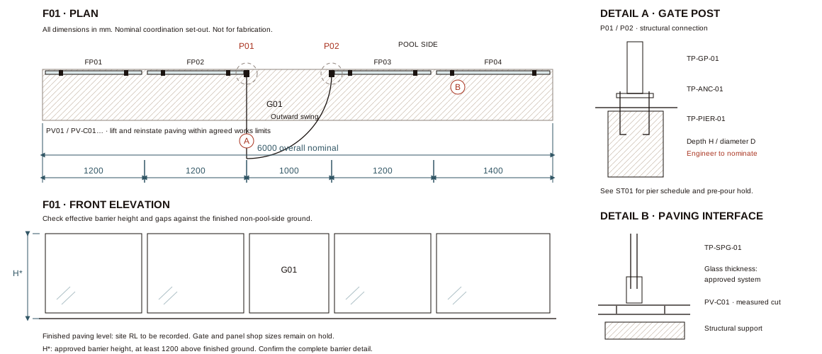
Set-out schedule
| Point / bay | Nominal chainage | Required site record |
|---|---|---|
| F01 origin | 0 | Verified survey datum; not an assumed boundary fence line |
| FP01 / FP02 | 0–1200 / 1200–2400 | Actual clear openings, top and bottom levels |
| P01 / P02 · gate posts | 2400 / 3400 | Easting / northing, RL and pier centreline |
| FP03 / FP04 | 3400–4600 / 4600–6000 | End return, wall condition and connection detail |
Read with the selected option
G02 is a separate measured gate bay for Options 2 and 3. Its location and dimensions require their own approved set-out. The natural-water option also requires coordination with planting and maintenance access.
For pool barriers, confirm the applicable approval and AS 1926 requirements with the building surveyor / certifier. Check finished-ground levels, gate operation and non-climbable zones across the whole enclosure. SA pool safety guidance.
Parts & fabrication schedule
Every gate, panel, fixing and reinstated paver has an internal reference that follows it from drawing to pick list to installation.
Procurement hold. These are True Point internal part numbers. Supplier catalogue SKUs, finishes, measured shop dimensions and structural fixing specifications must be matched and approved before ordering. Quantities below cover the F01 bay and nominated gate allowance, not the full pool perimeter.
| Part number | Drawing mark | Description | Quantity | Specification / cut information | Responsible trade | Installation instruction |
|---|
Each cut paver receives a PV-C mark with its original module, finished dimensions, notch position, location and edge finish. Record supplier SKU / batch and the installed mark in the as-built register. Gate kits include the matched hinges and latch; the component lines are traceability records, not duplicate order quantities.
Existing-site works & reinstatement
Alterations at an established property need a measured scope, protection of retained work and an agreed make-good responsibility.
Cut, remove, retain or remake
- Existing metal fencing: identify EX-F01 and the exact retained sections. Check corrosion, connections and stability before an approved cut or grind. Deburr, cap and restore the coating system.
- Toughened glass: do not cut, drill, notch or grind it on site. Confirm final dimensions and machining before toughening, or order a replacement panel. Glass processing reference.
- Tiles and pavers: mark the lift / saw-cut extent; photograph and label reusable units. Inspect the substrate and waterproofing. Measure closure pieces after post and spigot positions are settled.
- Make-good: reinstate matching paving, bedding, falls, movement joints and sealant. Keep drainage outlets clear and verify gate clearance against the final surface.
- Fixings: paving, tiles and screed alone are not the structural support. Refer edge distances, slab condition and post-tensioning to the engineer before drilling.
Latent conditions and variations
Stop the affected task, photograph the condition and raise an RFI when concealed services, poor concrete, unsuitable ground or a different fence line is found. Obtain an approved variation covering method, cost, time and reinstatement before resuming that work.
Before intrusive work
BYDA plans indicate infrastructure, not its exact position. Follow asset-owner directions and locate private services too. BYDA guidance.
Cutting, coring and grinding controls must address silica and other site risks. Assess whether a silica risk control plan is required. Use fit-tested RPE where required and prevent dust or slurry reaching occupied areas and drains. SafeWork SA guidance.
Bored piers & concreting handoff
The gate supports may need bored concrete piers below the existing paving. Their depth is a structural and ground-condition decision.
Engineering hold: D, H, C and L are not specified. The structural engineer must nominate pier diameter and depth, founding stratum / level, reinforcement, cover, concrete grade, post connection and required strength before loading. Do not assume a standard depth.
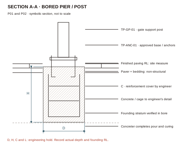
Pier record
| Mark | Set-out | Depth / founding | Release evidence |
|---|---|---|---|
| P01 | Nominal CH 2400; coordinates / RL to survey | H and founding RL by engineer; actual bore to be logged | Pre-pour record + concrete docket + strength release |
| P02 | Nominal CH 3400; coordinates / RL to survey | H and founding RL by engineer; actual bore to be logged | Pre-pour record + concrete docket + strength release |
Concreter’s scope
Engage a concreter for the pier works, including the agreed excavation, formwork, reinforcing, placement, compaction, finishing and curing. Check the contractor’s licence scope and nominated supervision. The fence installer coordinates the post template and receives the released support. SA licensing reference.
Crane delivery & installation day
A delivery brief for the crane contractor, dogger, installer and site supervisor. The crane contractor prepares the lift plan for the actual site and load.
Dispatch and lift hold. Do not dispatch against an assumed load weight, access width or concrete cure period. The manufacturer’s load data, crane contractor’s lift plan and receiving-site acceptance must agree.
Before the truck leaves
On the day, before the lift
Use the crane contractor’s nominated limits and procedures. This checklist is a coordination record, not a load chart, rigging design or SWMS. References: mobile cranes, general crane guide and high risk work licence classes.
Memorandum of understanding & handover
Record who supplies, prepares, installs and accepts each interface, including retained fencing and paving at an existing property.
| Party / role | Agreed responsibility | Handoff evidence |
|---|---|---|
| Client / site controller | Access, known site information, retained items, approved scope and the agreed variation process | Site condition record, access agreement and authorised variations |
| True Point / fabricator | Current drawing revision, internal part marks, verified shop details, supplier references and delivery manifest | Approved fabrication drawings and traceable parts schedule |
| Engineer / certifier | Structural details, footing requirements and the applicable design / inspection approvals within their engagement | Issued design, hold-point inspection and release records |
| Concreter | Agreed pier excavation, reinforcement, cast-ins, concrete placement, curing and records | Pier log, pre-pour record, concrete dockets and required test evidence |
| Fence installer / paving contractor | Set-out coordination, structural fixings, gate operation and the agreed cut, salvage and make-good work | Installation checks, measured cut list, as-built marks and photographs |
| Crane contractor / delivery crew | Lift planning, appropriate licensed personnel, plant, rigging, setup and controlled placement | Lift plan, pre-start checks, delivery docket and placement acceptance |
Agreed terms of the handoff
- The nominated quote option and drawing revision identify the work. A changed site condition or part substitution is recorded and approved before the affected work proceeds.
- Scope, payment, variations, delay charges, insurance and defects obligations remain governed by the signed building / supply contracts. Record any additional agreement by reference.
- Each party retains its own statutory duties. This MoU does not replace engineering approval, the building contract, a SWMS, the lift plan or required inspections.
- Unresolved items remain open at handover. An acknowledgement records the agreed responsibilities; it does not certify the barrier, release a footing or authorise a lift.
Completion and client handover
Install the required barrier before filling the pool. Arrange the approval and inspection steps applicable to this site, then provide operation and care information to the client. SA pool and spa safety.
Australian guidance used for this pack
Reviewed 9 September 2026. Use the approved drawings and requirements applicable to the location and work being undertaken.